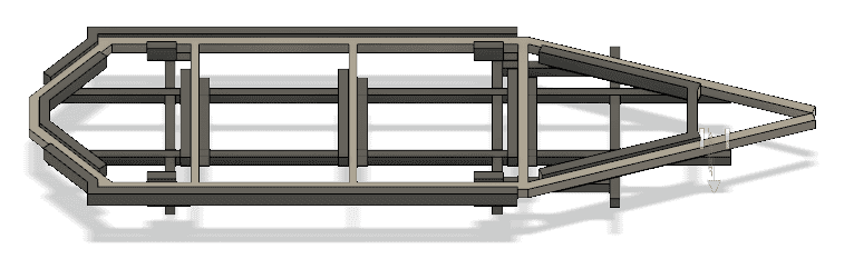
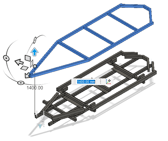
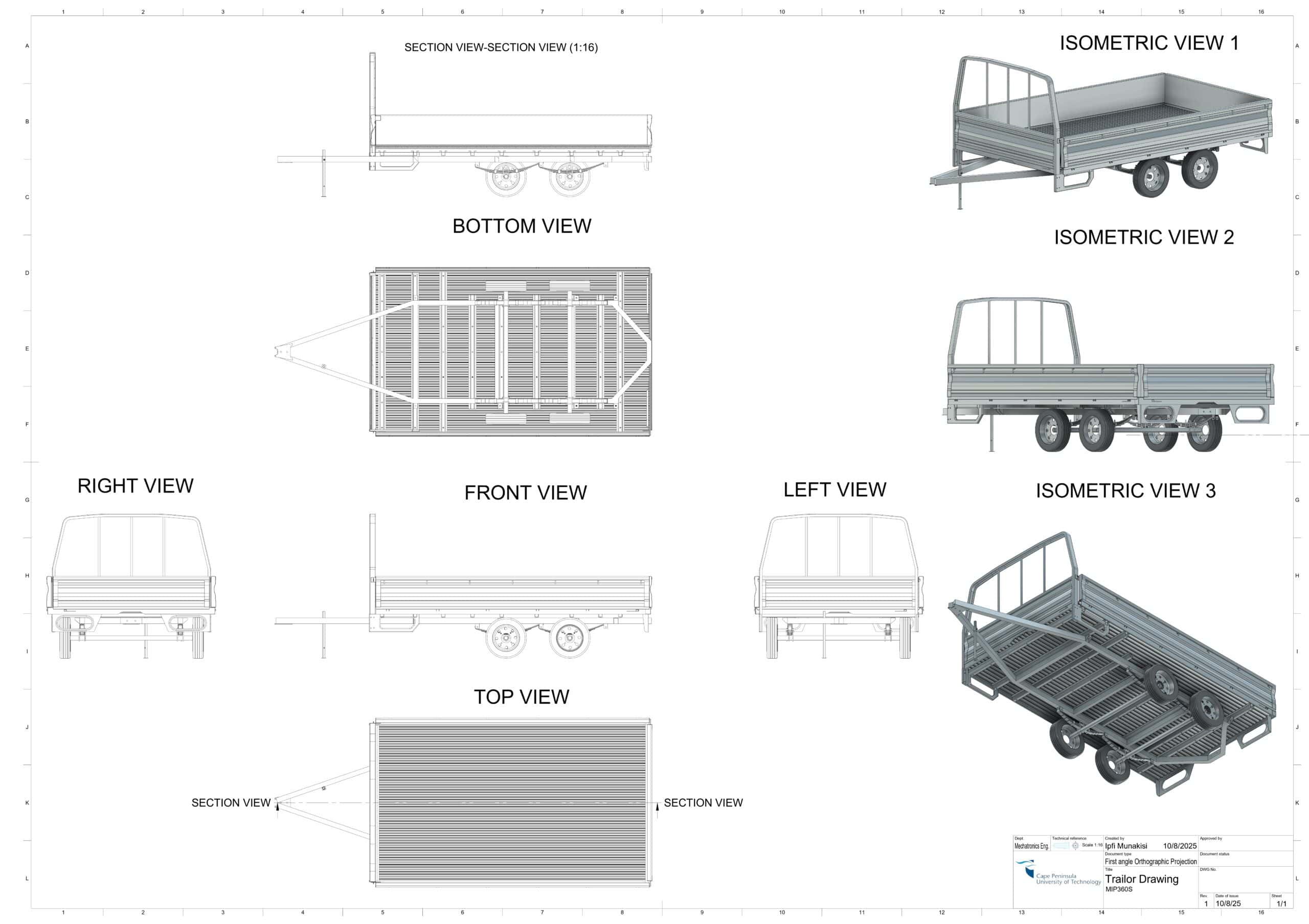
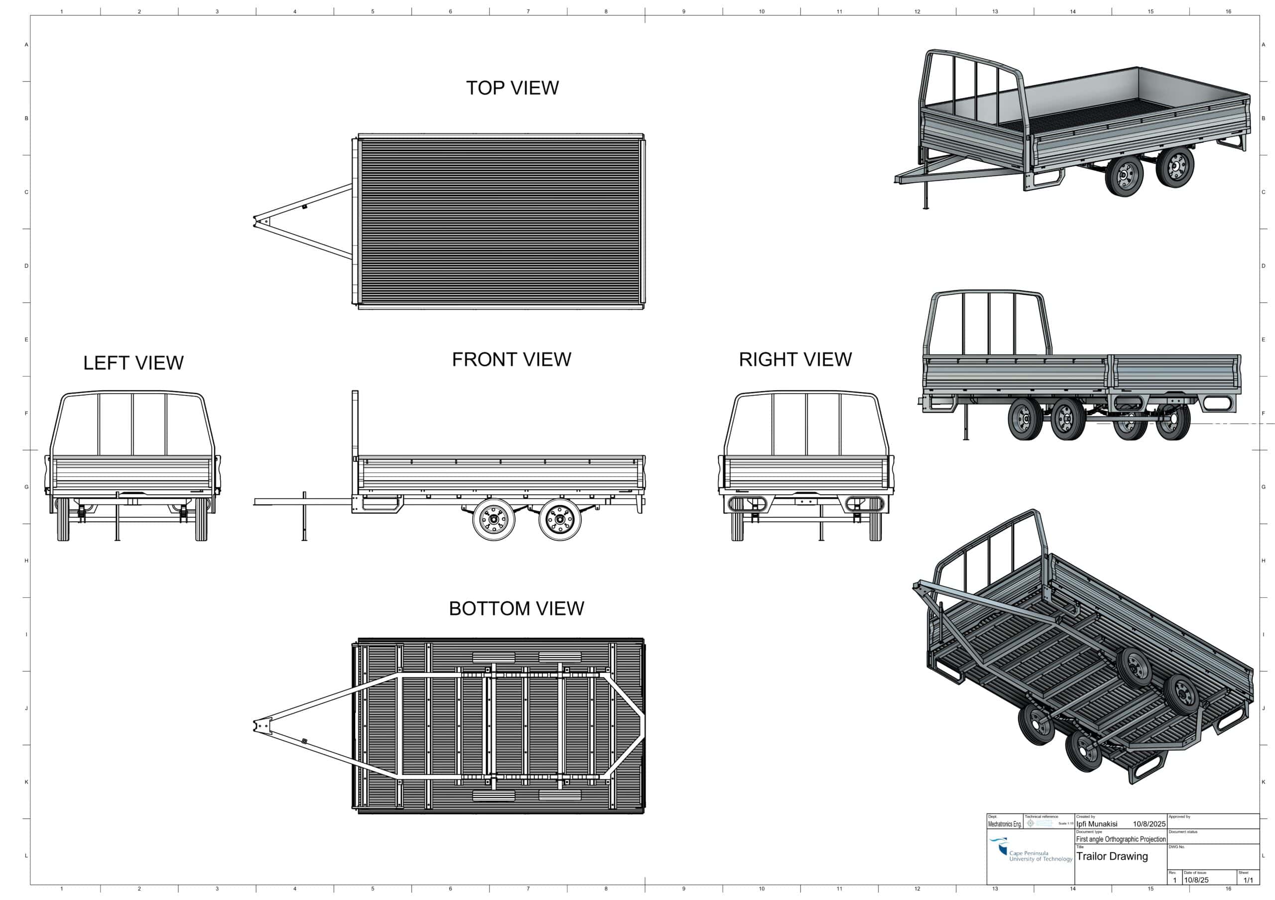
3d CAD Trailer Modeling
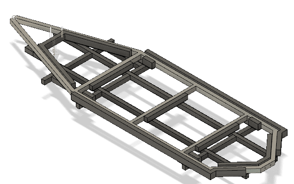
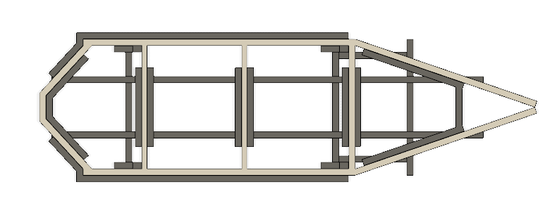
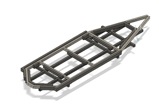
Microsoft Fusion360: Everything Modeled with the exception of imported wheels

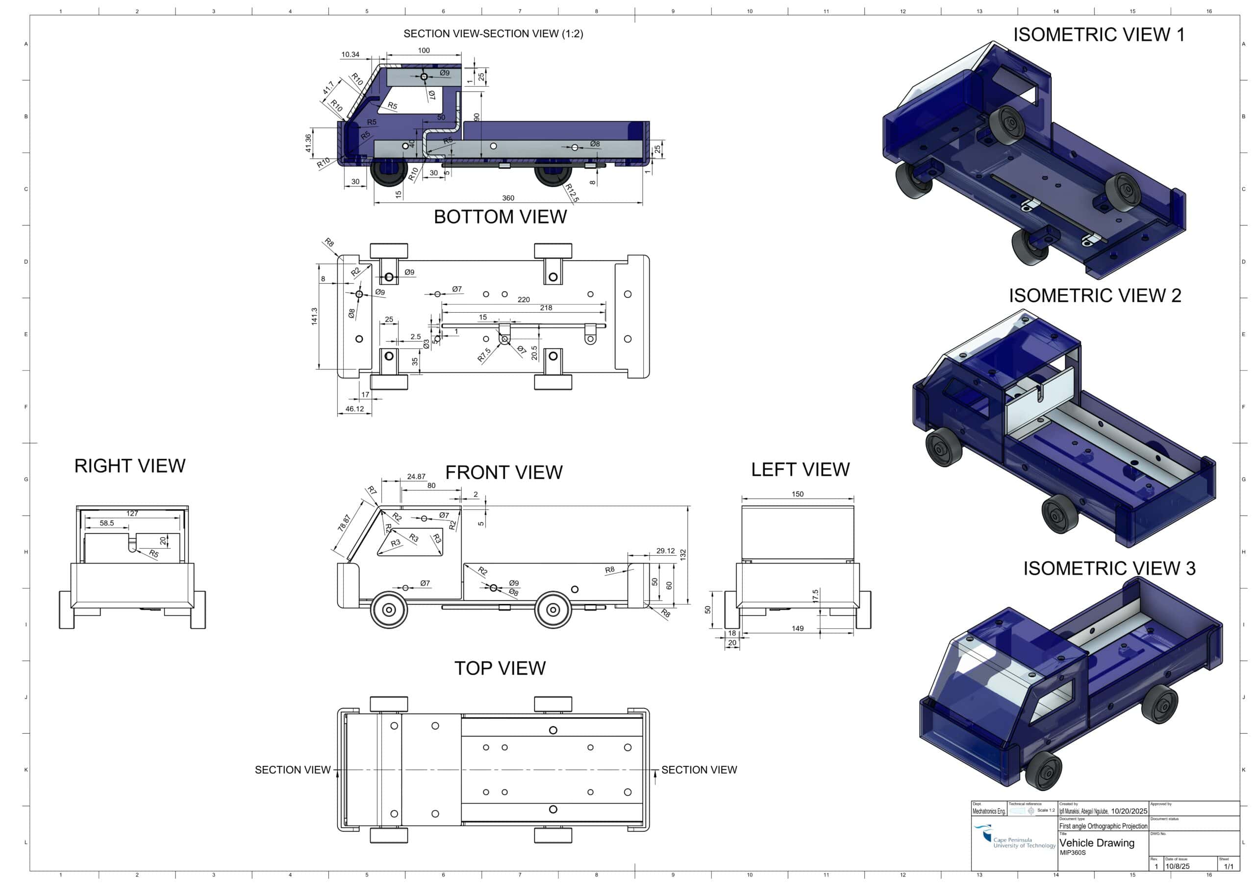
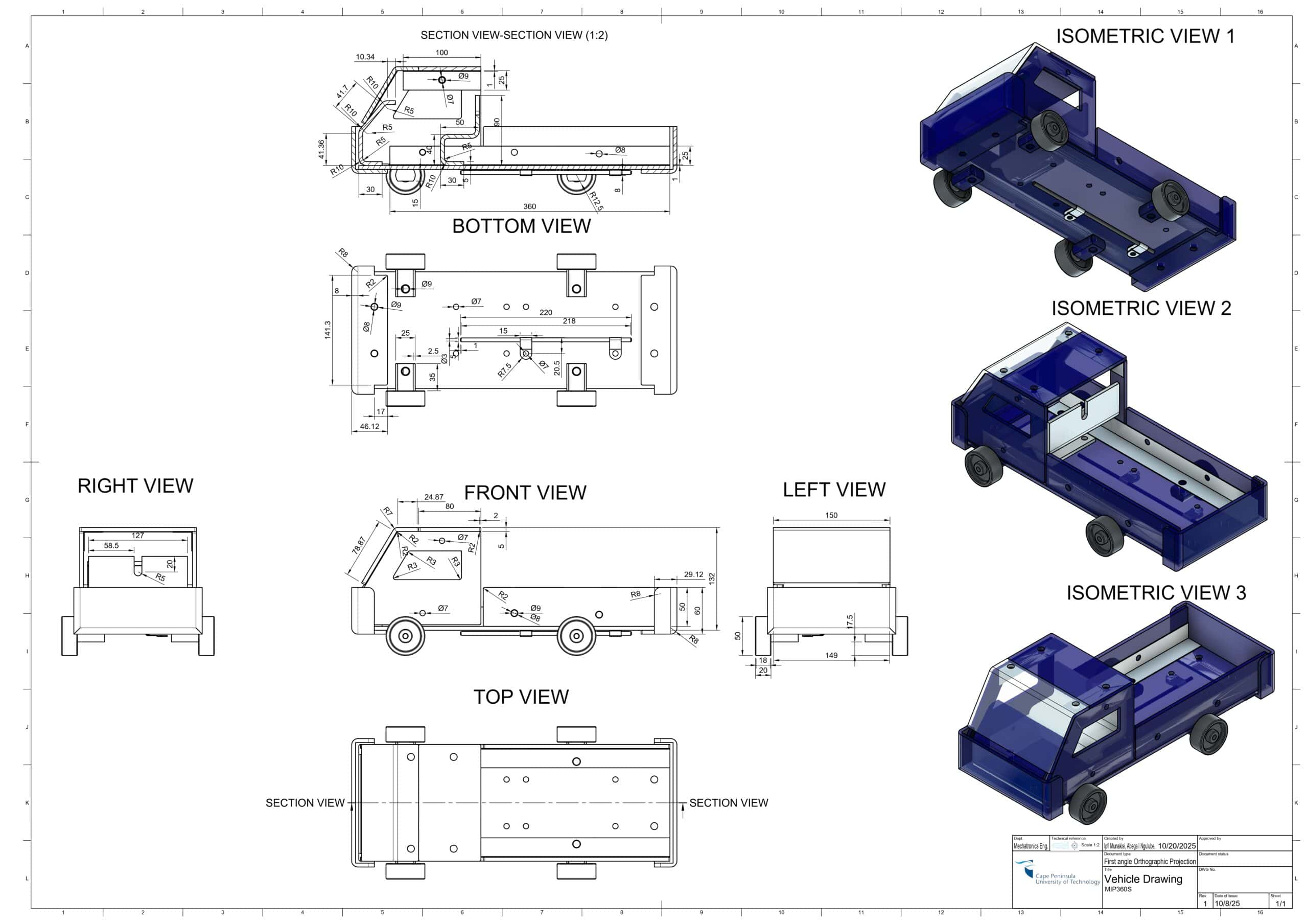
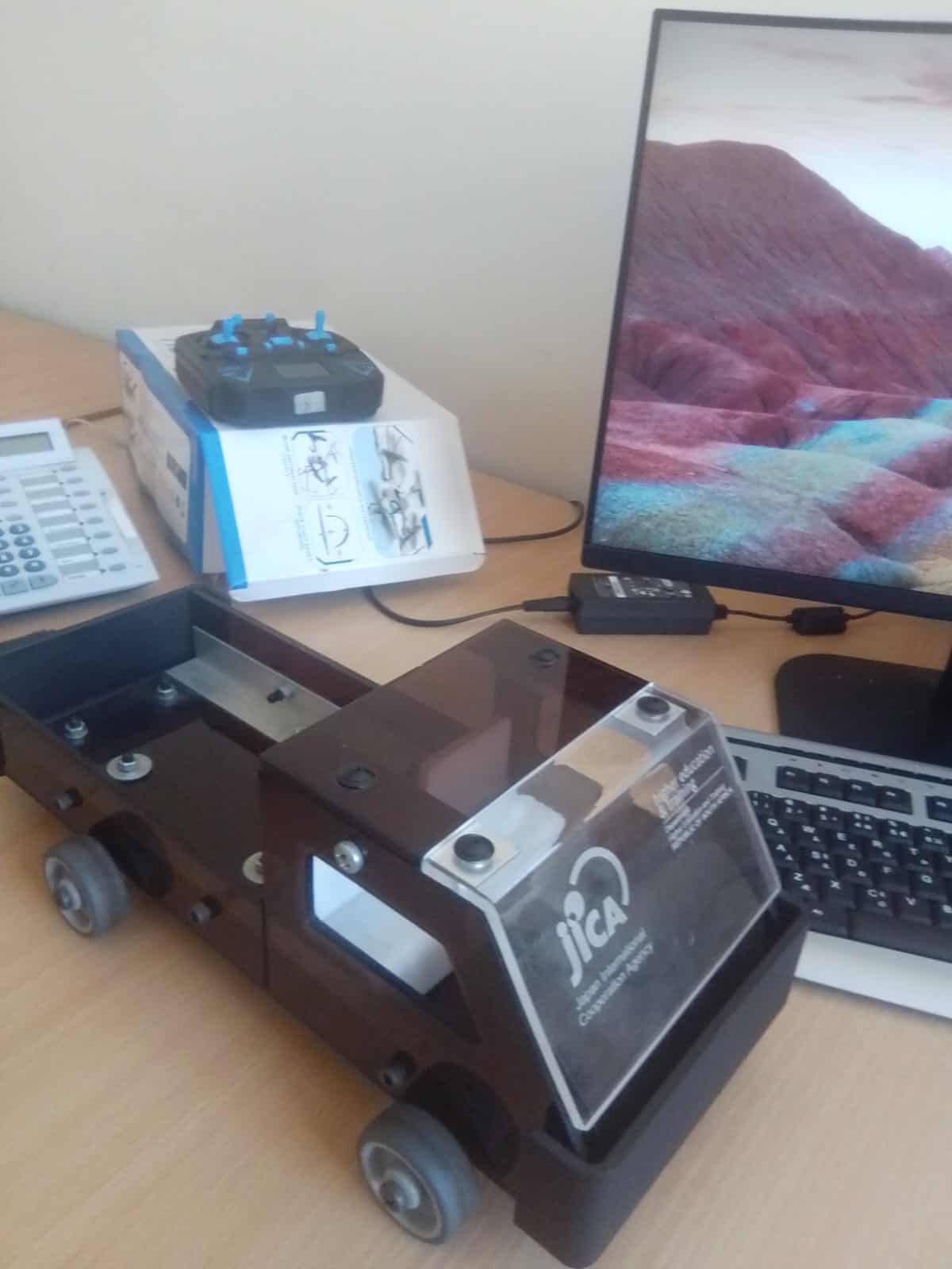
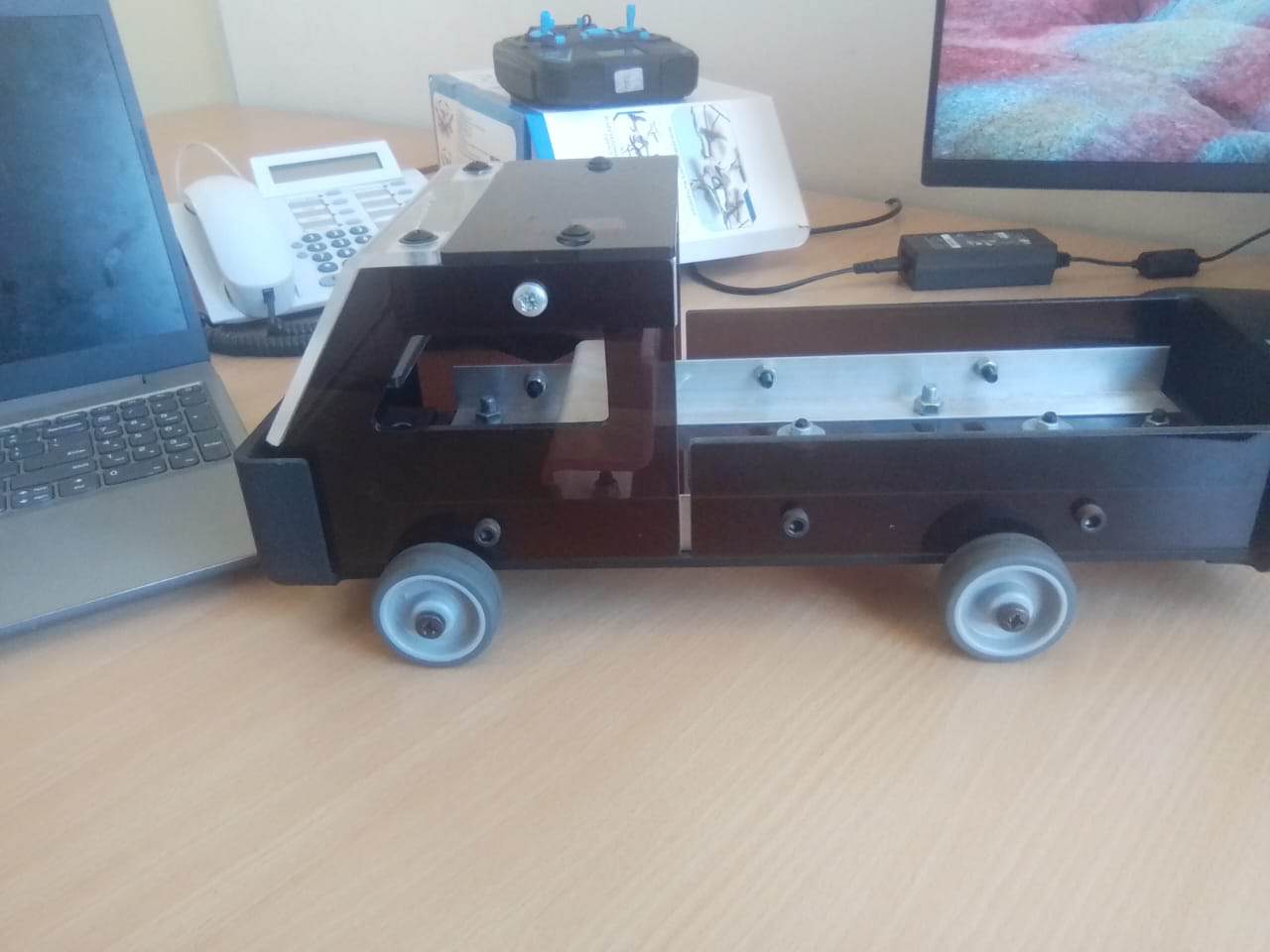
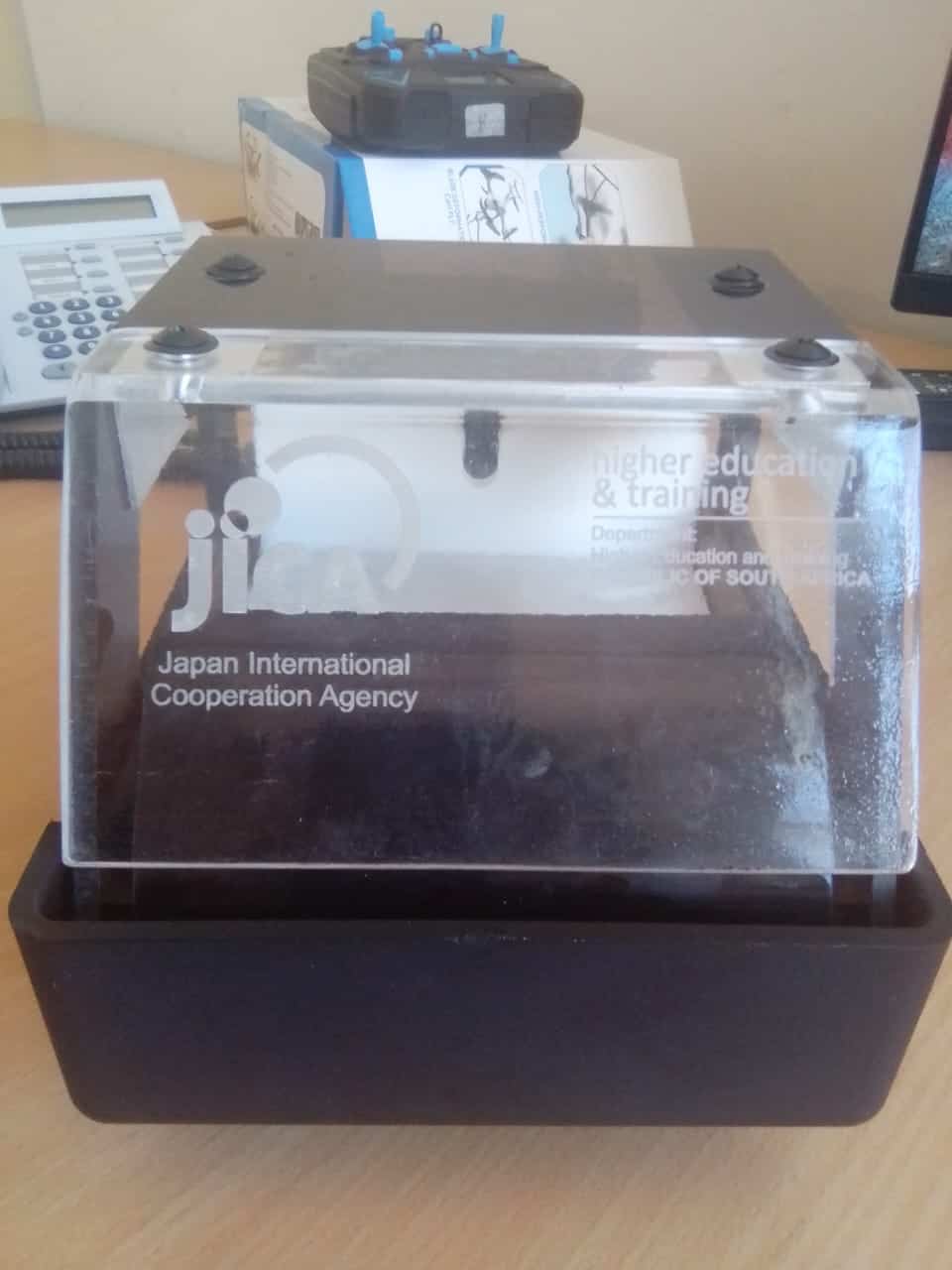
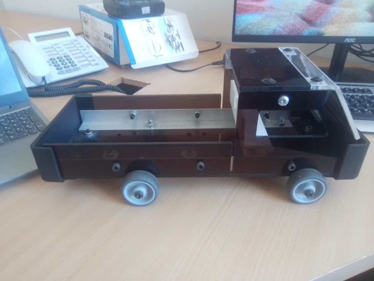
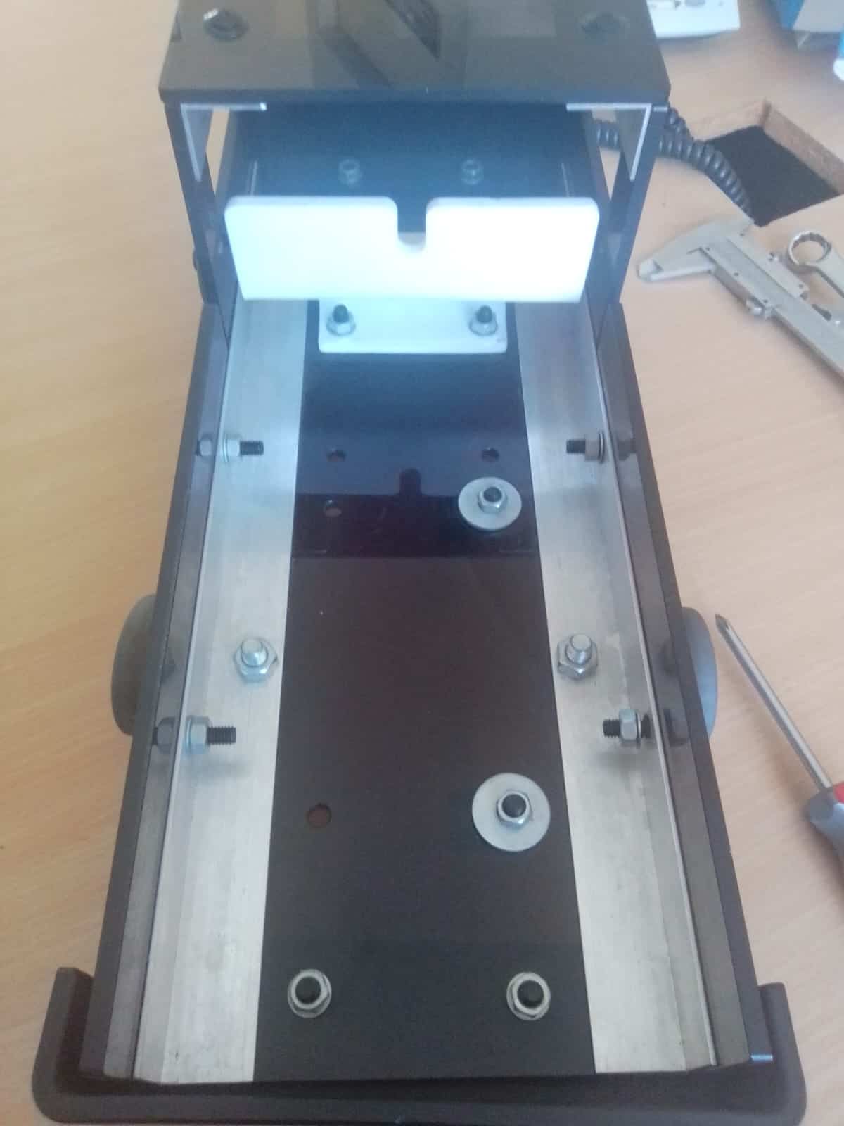
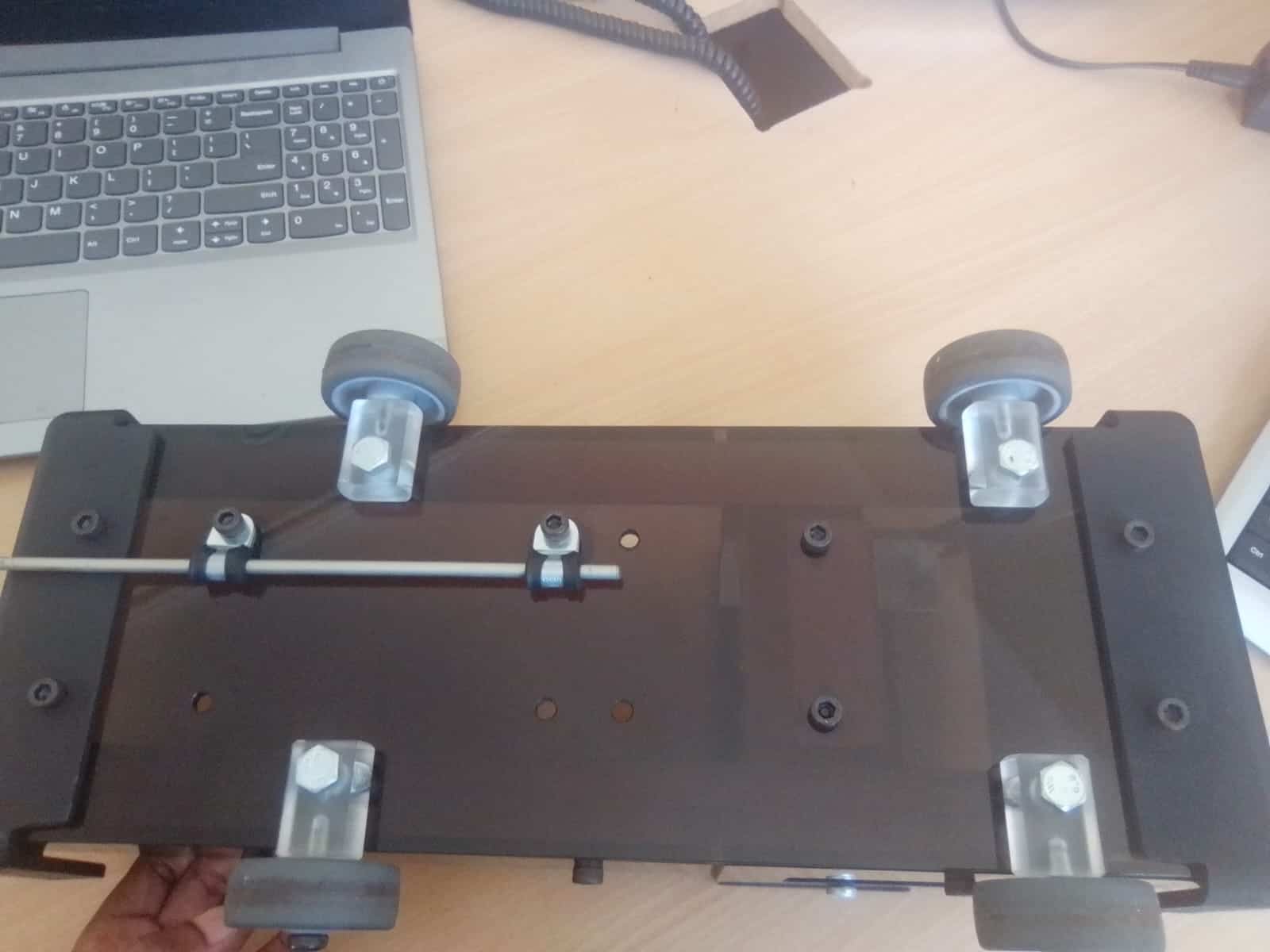
CPUT CAD Vehicle
Commissioned to assist departmental work. 80%+ involvement from design drawings to 3d animations
CPUT CAD Vehicle Exploded animation
Pap Cooking Device
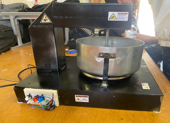
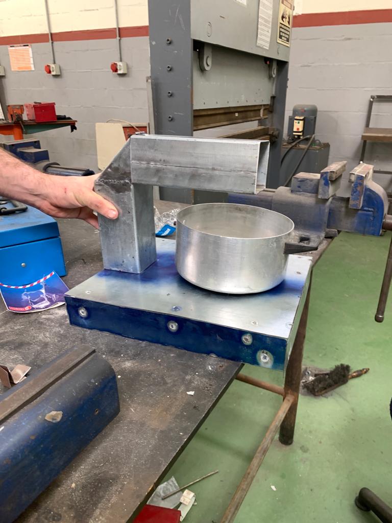
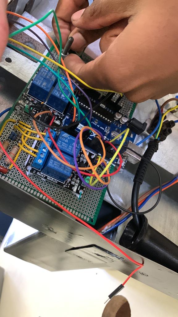
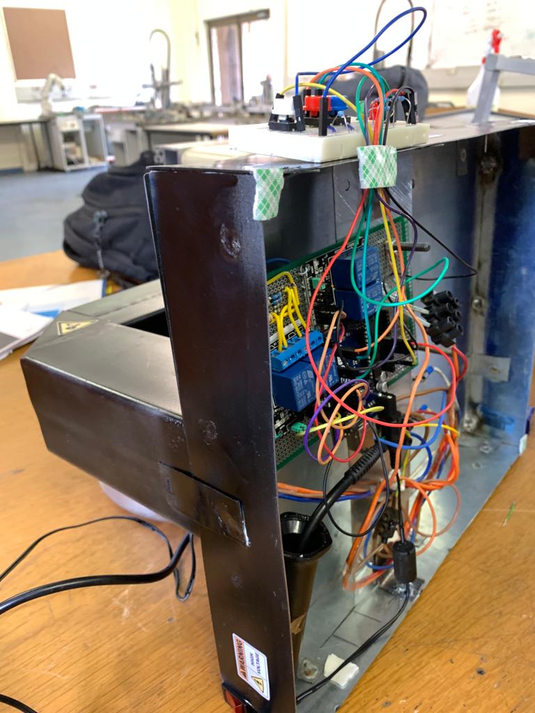
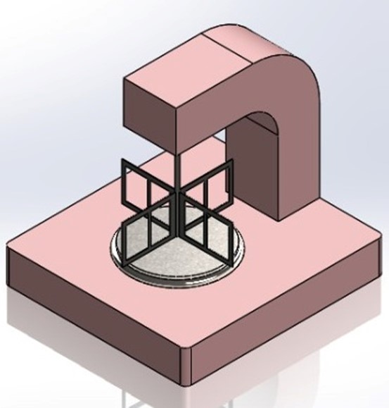
designed and developed a microcontroller-based pap cooking machine with automated functionalities for two distinct cooking styles (South African and Zimbabwean)
Project overview
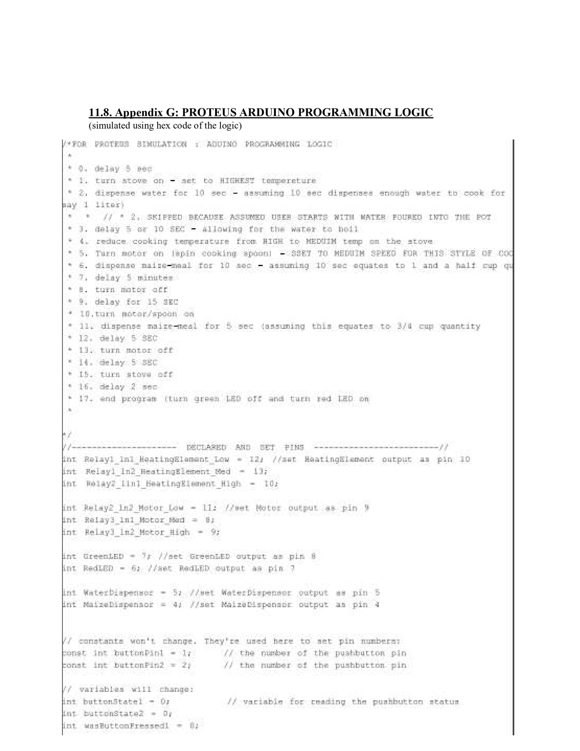
For this project, I was responsible for designing the electrical circuit/schematics, programming the Arduino microcontroller, and also assisted with simulations and physical assembly. The project achieved a distinction, and I scored 100% for my part of the actual presentation.
Key Features:
Automated cooking for four with programmable controls for temperature and motor speed.
Arduino-controlled low-voltage signals (0–5V) managing high-voltage circuits (220–240V).
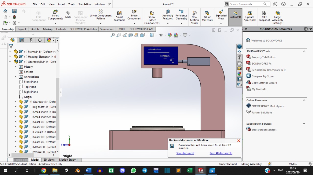
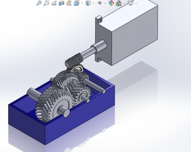
Gearbox optimized motor speed and torque for efficiency.
Highlights:
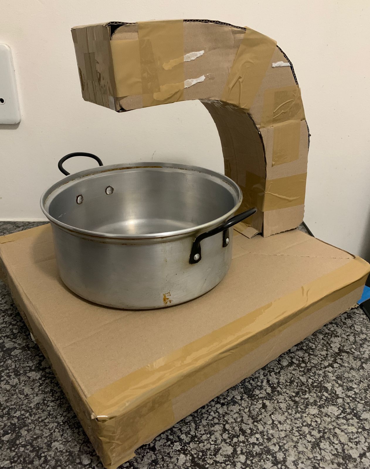
Chosen G-Type design for effectiveness after concept evaluation.
Created a low-cost, functional prototype as an alternative to manual cooking.
Enhanced skills in Arduino programming, circuit design, and teamwork.
This project illustrates innovative problem-solving, technical expertise, and collaboration to deliver a practical solution.
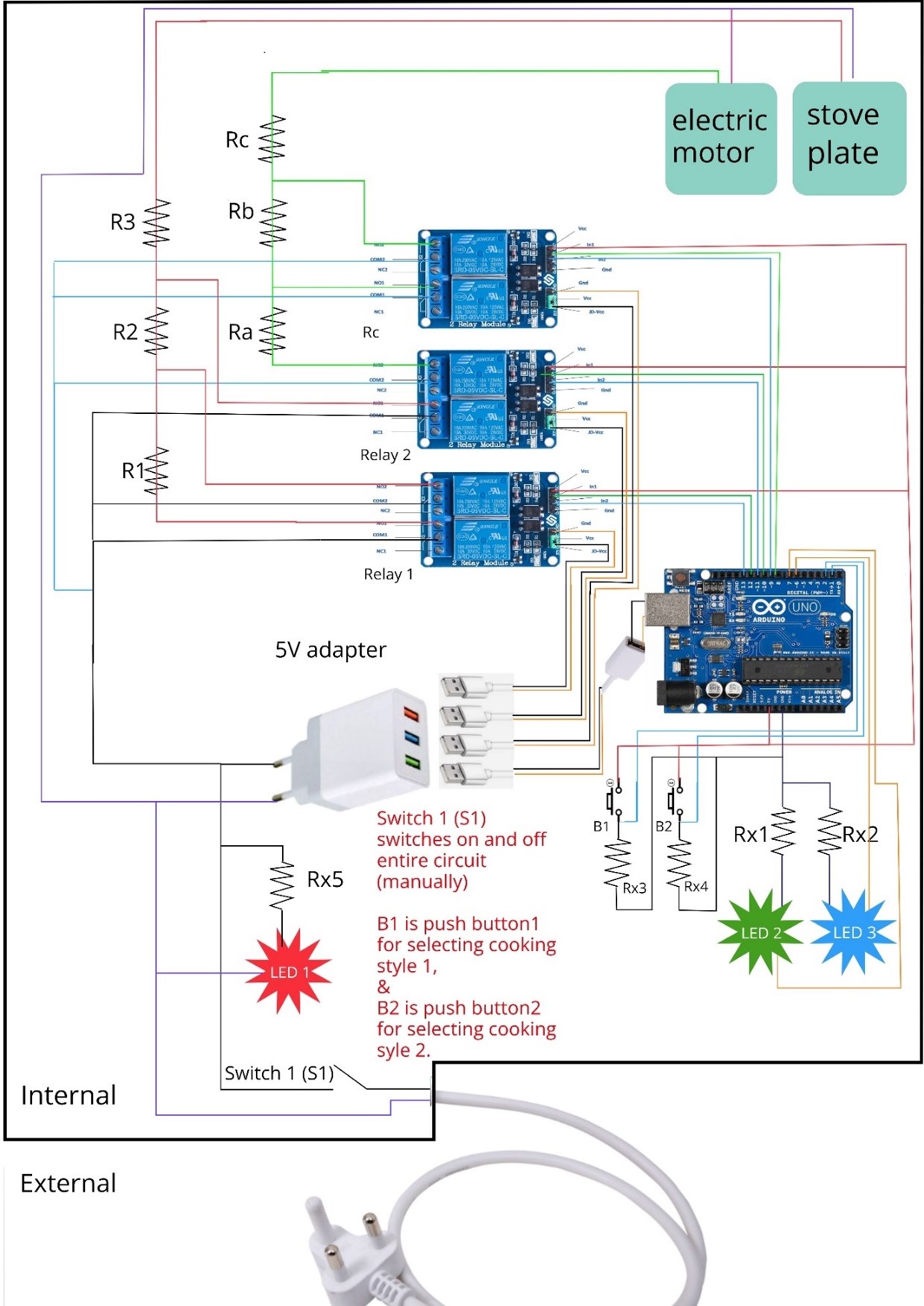
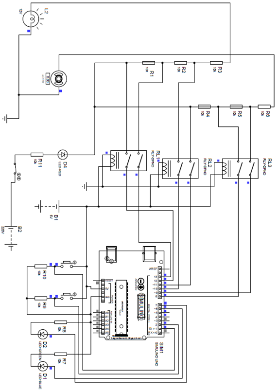
[Figure above]: Proteus simulation schematic
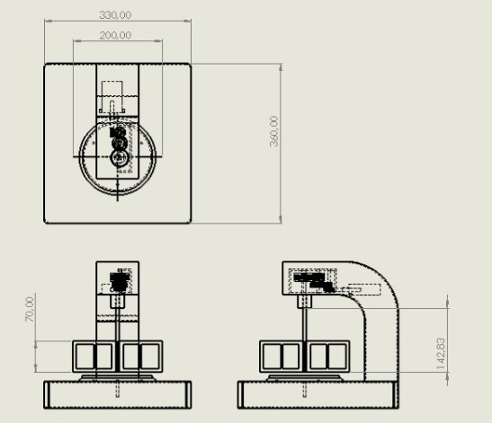
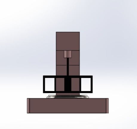
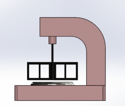
Pap, a daily staple world-wide, is still laboriously cooked by hand in many households today. The purpose of this project was to design a low budget microcontroller based pap cooking machine capable of cooking for 4 people and be able to cook pap with two different styles of cooking, a South African style as well as Zimbabwean style. The pap cooking device created is an innovative machine with a base housing a stove plate and a G-shaped arm above the base supporting an electric motor with a mixing spoon attached to it; all the while using low voltage signals (0V-5V) from an Arduino control system to control a high voltage circuit (220V-240V) consisting of the electric motor and stove plate. The circuitry of the system is such that the speed of the motor, as well as the heat temperature intensity of the stove plate can be controlled automatically by the programming logic in the embedded system/microcontroller. A gearbox, placed between the motor and the cooking spoon, was used to convert the hight 325 revolutions per minute (R.P.M) and low torque of 3.67Nm to a low 81.24 R.P.M and high torque of 14.68Nm. Multiple concepts were designed and evaluated using a decision matrix, and concept Two (the G-Type design) was chosen for further development into the final design as it met most of the criteria around solving the design problem presented. The authors/designers will showcase their novel Arduino controlled 2-styles pap cooking machine and hope to raise awareness around efficient alternatives to making pap.












Embedded Systems with PIC Microcontroller
7-Segmnet Display by Numeric Keypad Press
Project: Embedded Systems 7-Segment LED Display with Keypad Input
Developed and simulated an embedded system featuring a 7-segment LED display controlled by user input from a 4×3 numeric keypad, powered by a PIC16F887A microcontroller.
- Technologies and Tools Used:
- Microcontroller: PIC16F887A as the core processing unit.
- Programming: C language in MPLAB X IDE for logic development and compilation.
- Simulation: Proteus 8 software for circuit simulation before hardware implementation.
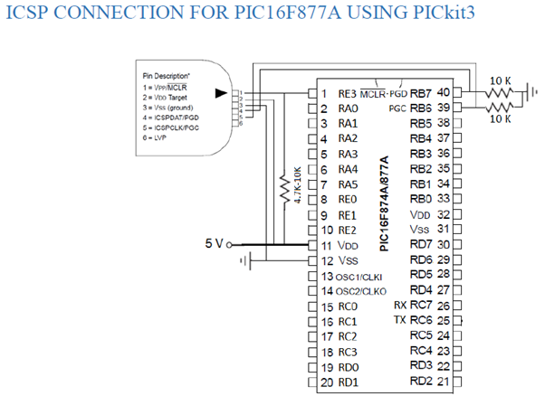
- Hardware Programming: ISCP connection adapter to transfer the compiled hex code to the PIC microcontroller’s flash ROM.
- Process Overview:
- Designed the circuit and programmed the microcontroller to manage inputs from the keypad and output corresponding numbers to the LED display.
- Simulated the system in Proteus 8 to ensure functionality before programming the physical device.
- Utilized a breadboard for testing; suggested transitioning to a soldered PCB for durability and improved performance.
- Outcome:
Successfully implemented a working system where keypad input dynamically updates the 7-segment display. This project showcased proficiency in embedded system design, microcontroller programming, and circuit simulation.
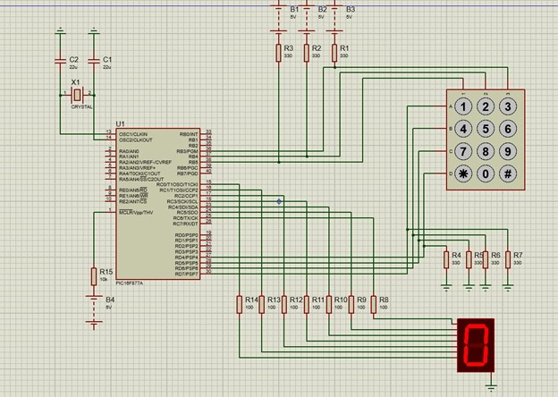
[Figure above]: Proteus simulation schematic
To conclude, one starts by answering the question of how “does everything work?” as that is the best way to recap everything done in this project and consequently its summary.
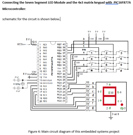
A 7 segment LED display with interrupts was designed and simulated. Essentially, an embedded systems of a 7 segment LED display, that will display/print/show the specific number on the it’s screen when a user presses that number input on the 4×3 number keypad. The whole process will be driven by a PIC16F887A microcontroller (the brain of our embedded systems). The overall circuit of our embedded systems is set up as per Figure 4: (Main circuit diagram of this embedded systems project).
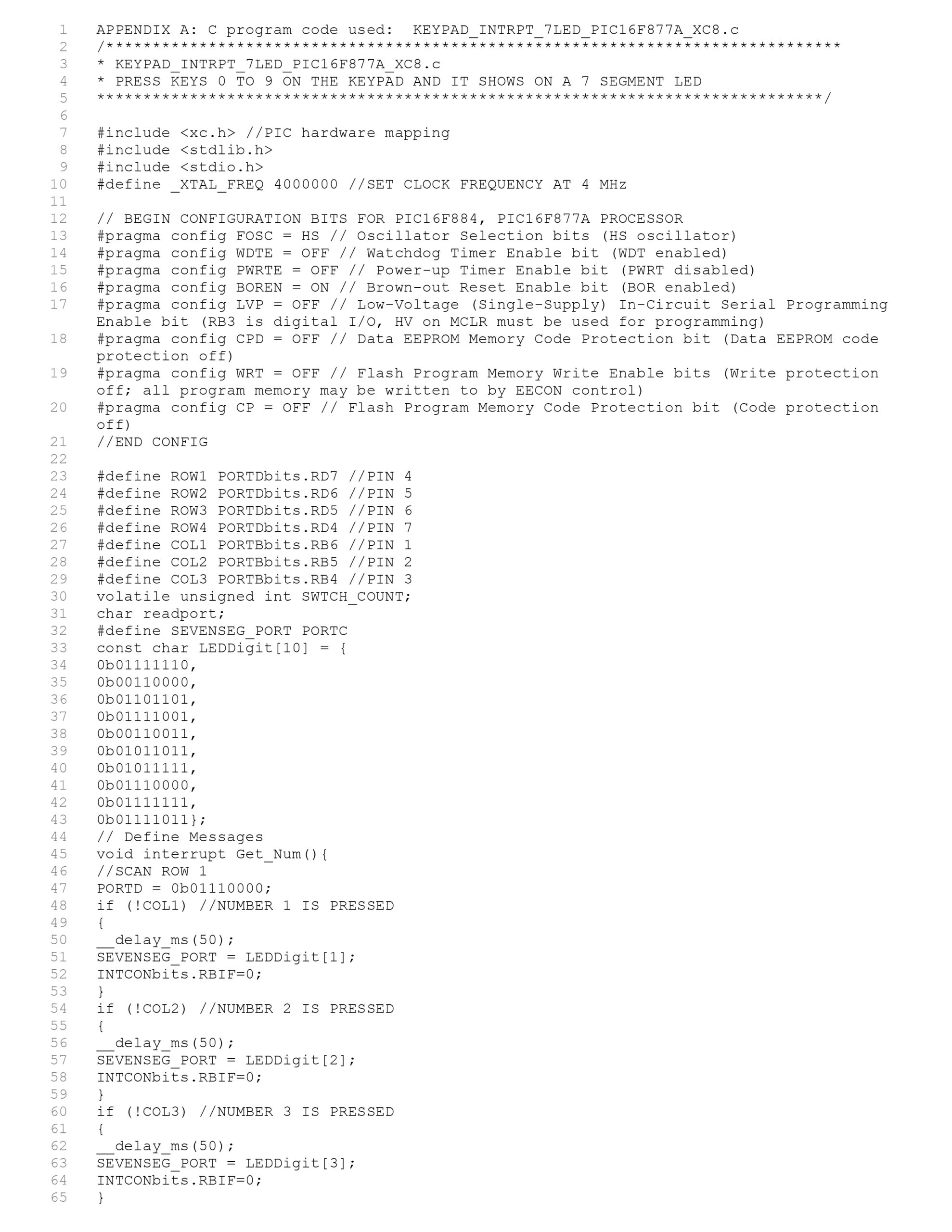
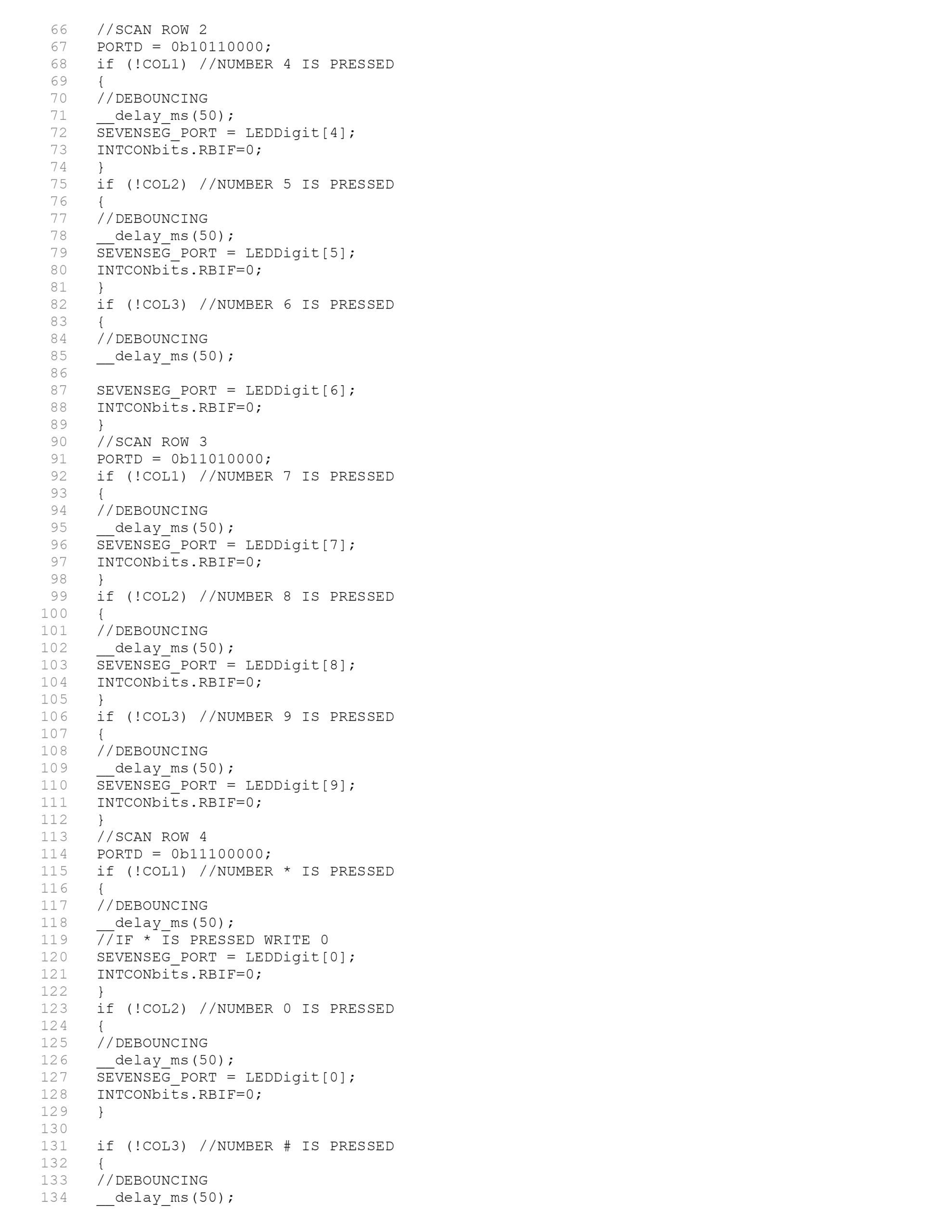
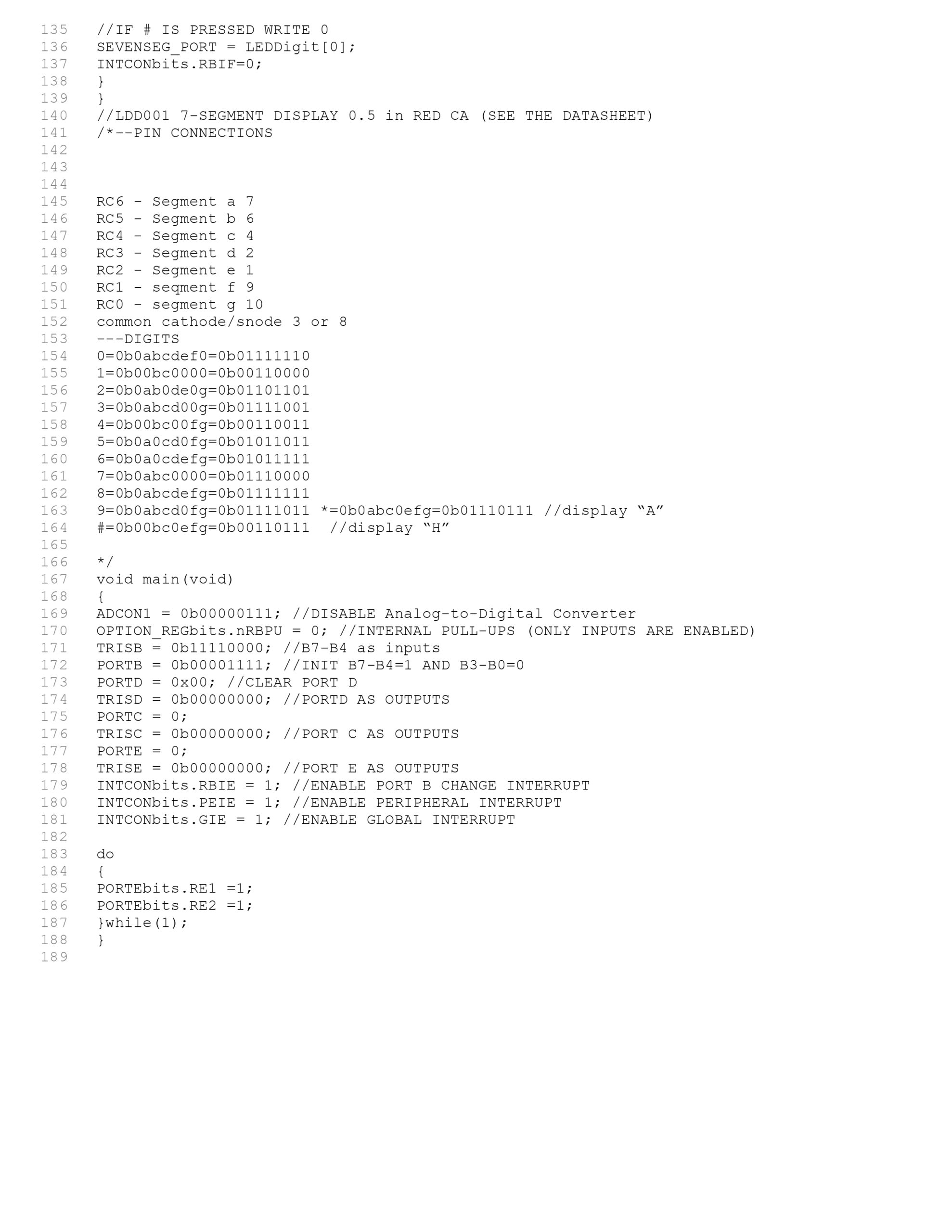
However, for a microcontroller to work, it needs a program of instructions to provide the logic of how the pic will manage the port in relation to sending relevant digital electrical signals that drive the overall embedded systems operations. Therefore, we first write our computer code (in our case this program is written in the c programming language right in the MPLAB X IDE) (MPLAB X, 2022). For this to happen, C programming language compilers must be configured on the MPLAB X IDE, the same is true for assemblers on the MPLAB which translate this code of our main program which will translate this code to binary machine language that allows our hardware to understand and execute code program instructions and execute them.
Before we program the PIC physical device, we first simulate the entire embedded systems in a simulation software called Proteus 8 (Proteus 8, 2022), and if all is working we then begin the process of programming our PIC microcontroller with the same code used in simulation.
We therefore transfer this code into our microcontroller in the CPU’s main memory (a non volatile flash rom memory) that will keep our program even when the electrical power is cut off from our. This transference of the hex (code) file is done with The ISCP connection adapter which is what actually does the programming on the microcontroller.
Once this is complete. Our embedded systems is ready and should working just fine, i.e, press a number on the 4×3 keypad matrix and that corresponding number will be displayed on the 7 segment LED display “screen”.
Project: Embedded Systems 7-Segment LED Display with Keypad Input
Developed and simulated an embedded system featuring a 7-segment LED display controlled by user input from a 4×3 numeric keypad, powered by a PIC16F887A microcontroller.
- Technologies and Tools Used:
- Microcontroller: PIC16F887A as the core processing unit.
- Programming: C language in MPLAB X IDE for logic development and compilation.
- Simulation: Proteus 8 software for circuit simulation before hardware implementation.
- Hardware Programming: ISCP connection adapter to transfer the compiled hex code to the PIC microcontroller’s flash ROM.
- Process Overview:
- Designed the circuit and programmed the microcontroller to manage inputs from the keypad and output corresponding numbers to the LED display.
- Simulated the system in Proteus 8 to ensure functionality before programming the physical device.
- Utilized a breadboard for testing; suggested transitioning to a soldered PCB for durability and improved performance.
- Outcome:
Successfully implemented a working system where keypad input dynamically updates the 7-segment display. This project showcased proficiency in embedded system design, microcontroller programming, and circuit simulation.
[Figure above]: Proteus simulation schematic
To conclude, one starts by answering the question of how “does everything work?” as that is the best way to recap everything done in this project and consequently its summary.
A 7 segment LED display with interrupts was designed and simulated. Essentially, an embedded systems of a 7 segment LED display, that will display/print/show the specific number on the it’s screen when a user presses that number input on the 4×3 number keypad. The whole process will be driven by a PIC16F887A microcontroller (the brain of our embedded systems). The overall circuit of our embedded systems is set up as per Figure 4: (Main circuit diagram of this embedded systems project).
However, for a microcontroller to work, it needs a program of instructions to provide the logic of how the pic will manage the port in relation to sending relevant digital electrical signals that drive the overall embedded systems operations. Therefore, we first write our computer code (in our case this program is written in the c programming language right in the MPLAB X IDE) (MPLAB X, 2022). For this to happen, C programming language compilers must be configured on the MPLAB X IDE, the same is true for assemblers on the MPLAB which translate this code of our main program which will translate this code to binary machine language that allows our hardware to understand and execute code program instructions and execute them.
Before we program the PIC physical device, we first simulate the entire embedded systems in a simulation software called Proteus 8 (Proteus 8, 2022), and if all is working we then begin the process of programming our PIC microcontroller with the same code used in simulation.
We therefore transfer this code into our microcontroller in the CPU’s main memory (a non volatile flash rom memory) that will keep our program even when the electrical power is cut off from our. This transference of the hex (code) file is done with The ISCP connection adapter which is what actually does the programming on the microcontroller.
Once this is complete. Our embedded systems is ready and should working just fine, i.e, press a number on the 4×3 keypad matrix and that corresponding number will be displayed on the 7 segment LED display “screen”.
Beam Section Design Optimization
Beam Section Design Optimization. (Report attached)
Addressed a mechanical design challenge involving the bending of beams. as highlighted by Budynas and Nisbett (2020). The project aimed to redesign a statically indeterminate I-parallel flange beam section to prevent failure through plastic deformation, ensuring cost-effectiveness and structural integrity.
- Analysis and Findings:
- Evaluated multiple beams (30 kg/m, 25 kg/m, 67 kg/m, and 75 kg/m) based on deflection, bending stress, and safety factor.
- Identified a 25 kg/m beam as the optimal choice for balancing deflection (4.31 mm) and stress (199.64 MPa).
- Determined that a 75 kg/m beam was the preferred option for a 1.6 mm deflection limit unless lighter beams were more cost-effective.
- Key Metrics:
- Initial beam (406 x 178 mm x 60 kg/m): Deflection = 1.7814 mm, Stress = 82.41 MPa, Safety Factor = 4.05.
- 30 kg/m beam: Deflection = 13.065 mm, Stress = 604.95 MPa, Safety Factor = 0.55 (failed).
- Outcome:
Developed a comprehensive approach combining deflection and stress analysis for safe, cost-effective beam selection. This project provided valuable insights into beam design for practical engineering applications.
SYNOPSIS
(Budynas, Nisbett,2020) The problem of bending of beams probably occurs more often than any other loading problem in mechanical design. Shaft, cranks, springs, levers, brackets, and wheels, as well as many other elements must often be treated as beams in the design and analysis of mechanical structures and systems. The purpose of this design project was to explore ways in which a design modification that requires a complete change of statically indeterminate standard I-parallel flange sections (as the only available section with Young’s modulus of 220 GPa) can be done given specific beam deflection limits whilst ensuring the beam does not fail, all this with a cost-effective approach. The arrangement of which was such that a beam is fixed at the wall and simply supported at the other and in the initial arrangement a beam section with specifications: 406 x 178 mm x 60 kg/m was used. In modelling the problem, the weight force acting on the beam was considered (Appendix D shows the unconsidered case), it was found that the maximum deflection was 1.7814mm, the maximum bending moment was 87.3590625 KNm, the maximum bending stress was 82.41 MPa, and the factor of safety was 4.05. The average yield strength for mild steel σ=335MPa (Drotsky,2011) was used as the point in which the stress in no longer directly proportional to strain in accordance with the modulus of elasticity and no longer obeying hook’s law, a point after which the beam loses it’s ability to revert back to its original position after the load exerted on it is removed; a point after which plastic deformation takes place and the beam deforms permanently.
Sometimes it’s not enough to say that the beam meets deflection requirements and therefore its safe. Bending moment stresses were calculated and compared to the average yield strength for mild steel σ=335MPa to check for safety, if the beam section’s bending moment stress was less than the 335MPa yield strength, the beam was considered suitable, especially if it weighed less per meter, as heavy beams can be costly. A 30kg/m was considered where it was found that the maximum deflection was 13.065mm, the maximum bending moment was 85.9795 KNm, the maximum bending stress was 604.9529MPa, and the factor of safety was 0.553762088. The stress analysis revealed stress levels beyond the material’s yield strength, suggesting potential failure. A 25kg/m was considered where it was found that a 25 kg/m beam offered the best compromise between deflection and stress. With a deflection of 4.31 mm and a stress of 199.64 MPa, it proved to be safer than the 30 kg/m beam. This is the recommended choice. To find the most economical option for a deflection limit of 1.6 mm, deflection limits were compared using the excel validation tool developed. The 67kg/m beam has a maximum deflection of 1.58 mm, just under the limit, with the only other beam having a deflection limit under 1.6 mm being the 75kg/m beam (1.41 mm the preferred choice). In combining two beams approach, essentially doubling the second moment of inertia of the beams, the excel validating tool showed that the 39kg/m and 46kg/m beams were both under 1.6 mm. If acquiring two lighter beams is cheaper than one 75kg/m beam, the lighter beams should be chosen; otherwise, the 75kg/m beam remains the preferred choice.
Roller Conveyor Design
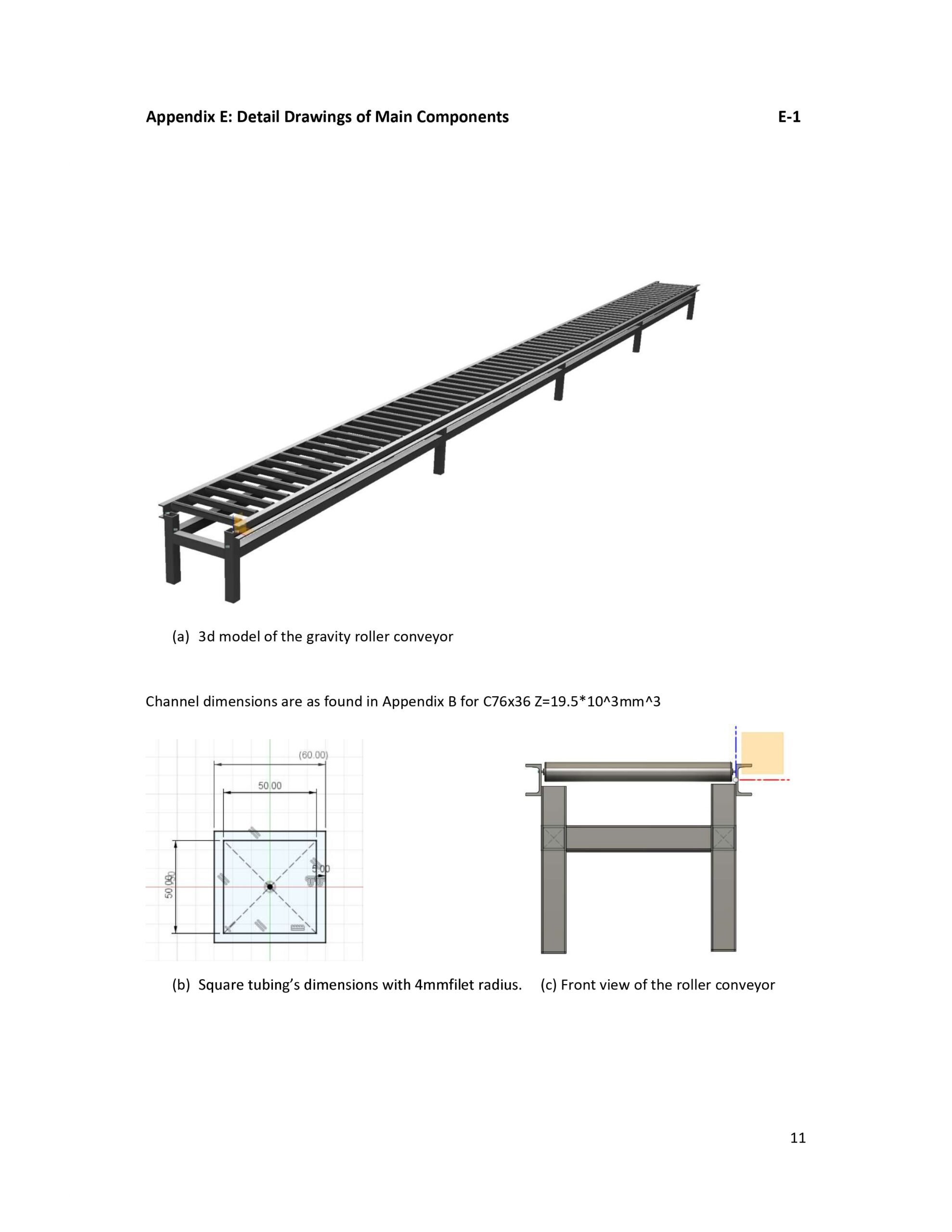
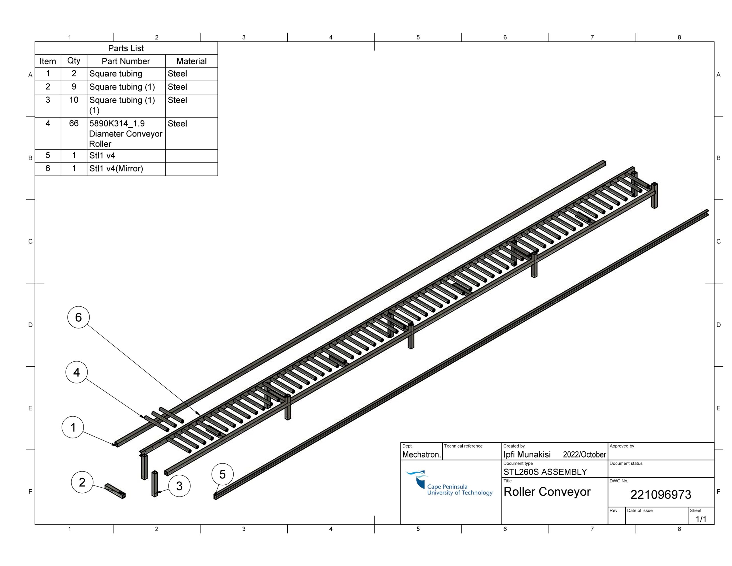
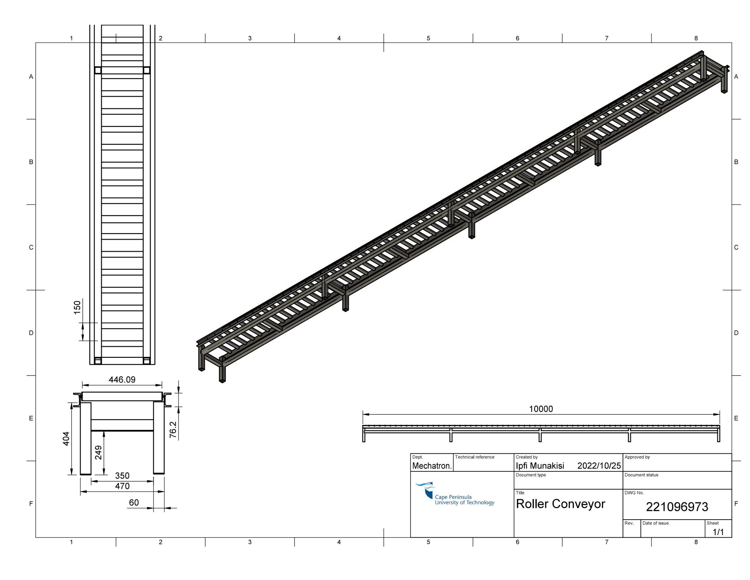
Designed a 10-meter gravity-powered roller conveyor to support up to 100kg without structural failure, addressing elastic deflection and general yielding modes of failure.
- Approach and Analysis:
- Case 1: Initial beam (Z=150×10⁶ mm³) failed due to excessive bending stress (6441260 N·mm²). Upgraded to a larger beam (Z=364×10⁶ mm³) with reduced stress (25.4 N·mm²), but it proved too heavy (34.8 kg/m).
- Case 2: Redesigned with intermediate supports every 2 meters. A lighter C-channel beam (6.7 kg/m, Z=19.5×10⁶ mm³) reduced stress to 19.5 N·mm² and deflection to 0.000001395 mm, meeting design criteria.
- Case 3: Accounted for roller weights as distributed loads. The beam maintained safe stress levels (23.5 N·mm²) and deflection (0.000001681 mm).
- Outcome:
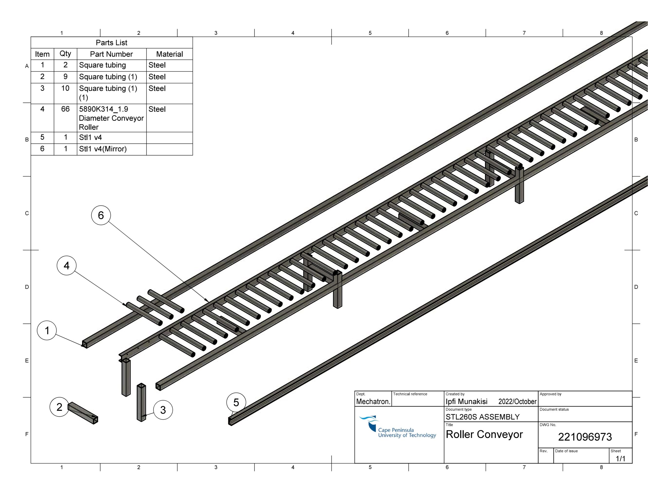
- Developed CAD drawings based on Case 3 design.
- Validated results using Excel and a custom C program for beam selection.
- Selected mild steel with anti-corrosive treatment; rollers sourced from McMaster-Carr.
Delivered a cost-effective and structurally sound design, successfully meeting project goals.
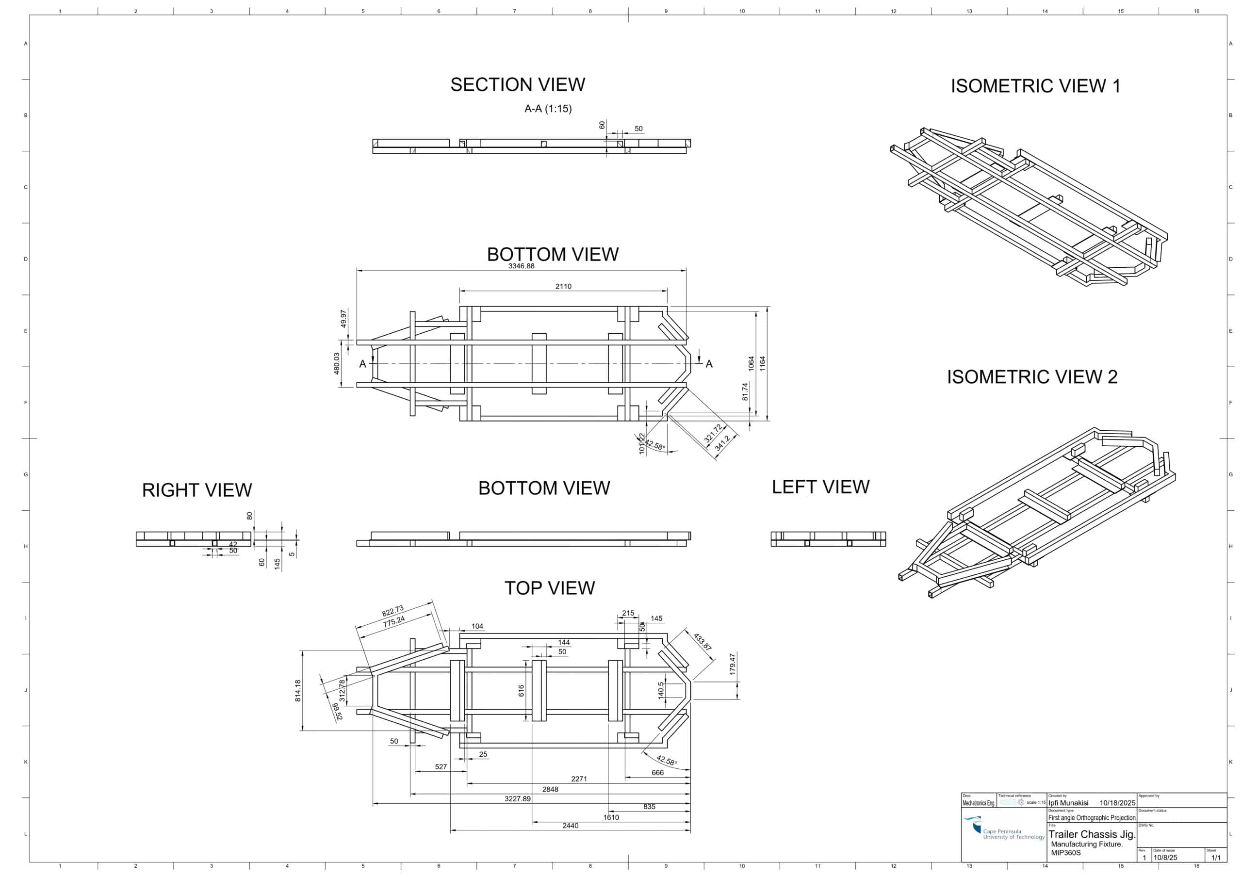
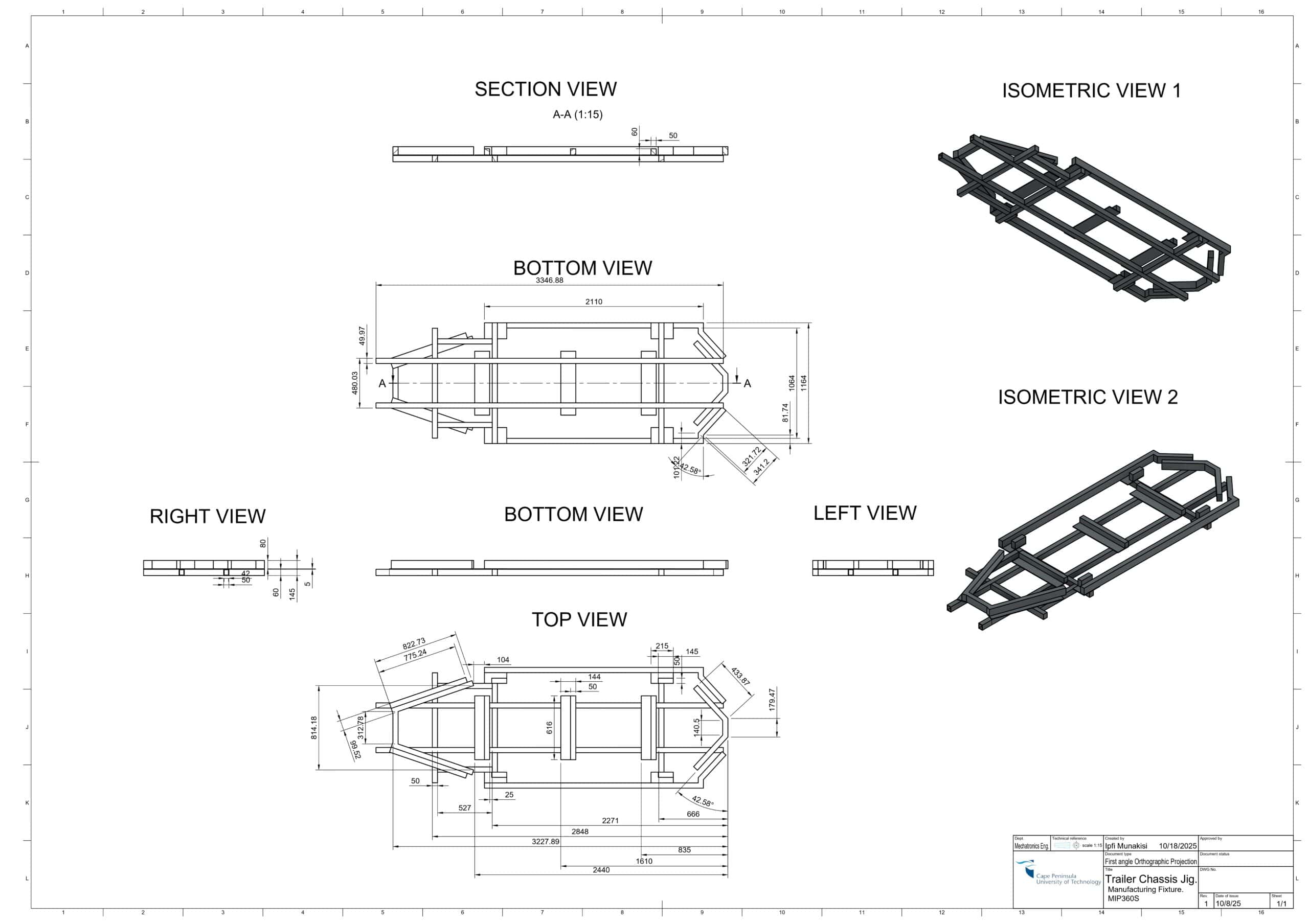
Engineering drawings
Design of a Home Wind Turbine System
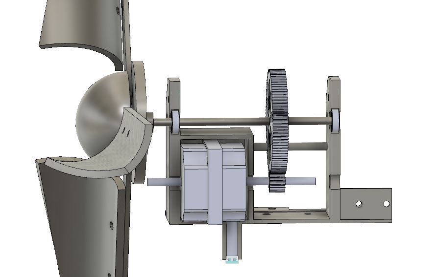
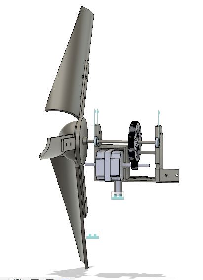
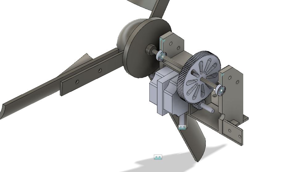
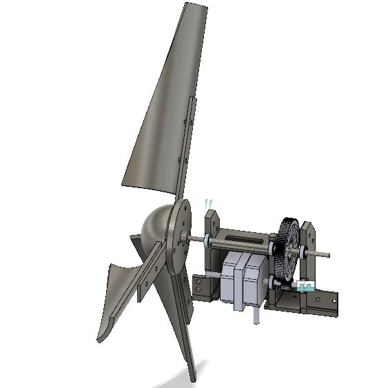
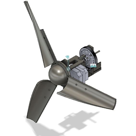
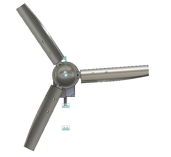
Final 3d-print ready CAD model
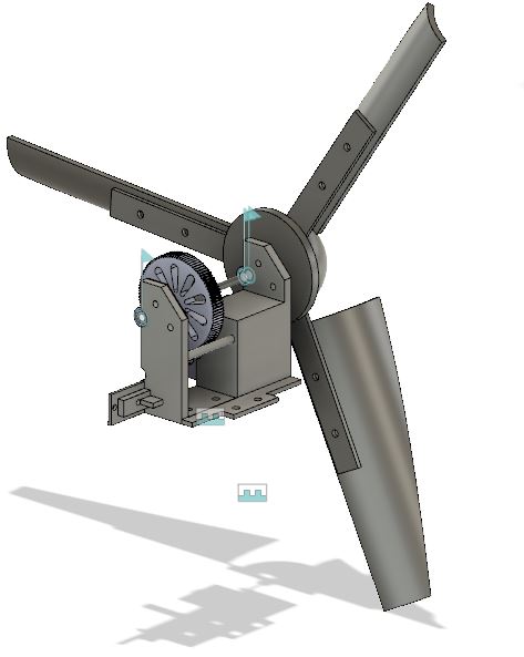
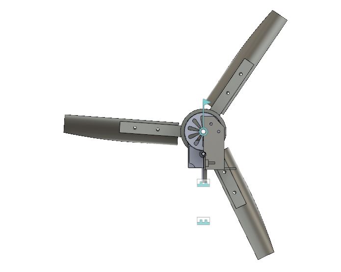
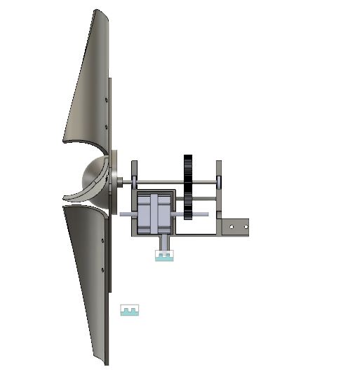
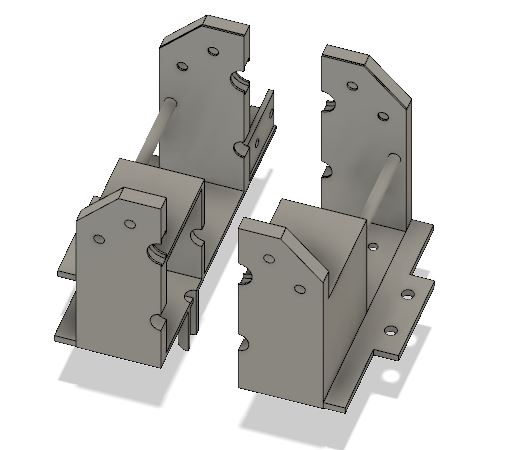
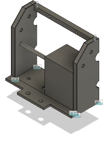
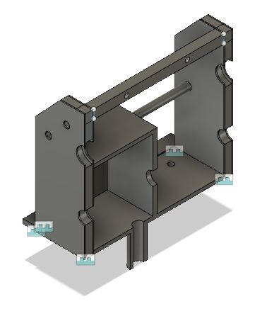
3d Printed gears
Concept formation 8 (my design)
9.5 5. Concept 8
A concept design of a home wind turbine system with an aim of generating 100 watts… This concept uses a 3 blade design in (1) connected to chain drive in (2), which transmits rotational speeds to (3) the car alternator which acts as a generator producing rectified DC voltage electricity which is connected to (4) a charge regulator module which charges (5) the car battery of 12v, 9ah and 108 watts which is connected to (6) a DC inline watt meter for power monitoring; a load can be connected at (7) a 12v to 5v DC step down converter, and (8) a 3 way switch connected to 3 DC LED light bulbs in (9)
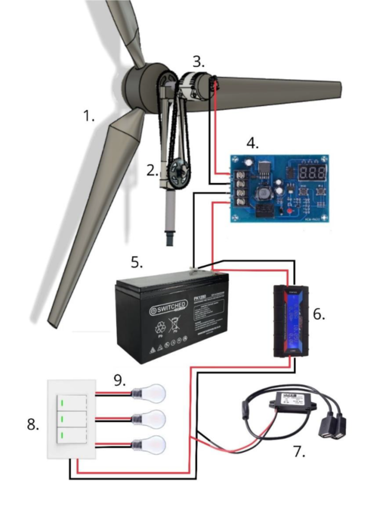
1. Wind Turbine Blades: The wind turbine blades will be designed to efficiently capture wind energy at low wind speeds.
In determining the ideal wind blade design for project (considering constraints), several factors are considered:
a. Aerodynamic Efficiency:
Small-scale wind turbines have an efficiency ranging from 20% to 40%. For this analysis, let’s assume an average efficiency of 20%.
b. Blade Length and Sweep Area: Assuming a rotor diameter (D) of 1 meter, the blade swept area (A): A = π * (D/2)^2 = π * (1.2/2)^2 = 1.13 square meters
c. Blade Shape: 3 blades design (can be made 6)
d. Material Selection: PVC for ease of fabrication and feasible practical application.
e. Blade Angle of Attack: higher angle of attack and a lower angle of attack towards the tip.
f. Balanced and Simmental: For low vibrations, noise, smooth operations and longevity.
Page | 22
2. Gear Chain Drive: A bicycle gear chain drive with gear ration of (large sprocket 42 teeth/11 teen small sprocket = 3.88 which is approximately 4 (meaning for every 1 revolution of the blade connected to the large sprocket, the small sprocket will rotate 4 time;
Since the gear ration is 4 between the large and the small sprocket.
When Large sprocket 1 (connected to the Blade) rotates once, the small sprocket 1 rotates 4 times. Large sprocket 2 is also connected to small sprocket 1 (meaning they rotate at the same speed). (At this point, please note that large sprocket 1 is not directly connected to small sprocket 2(although this is not so obvious from the 3d CAD model).
When Large sprocket 2 rotates once, small sprocket 2 rotates 4 times (which is connected to the car alternator/generators.
Therefore, when the blade makes one revolution (rotates once), the car alternator makes 16 revolutions!
If for example the blades rotate 60 times per minute, then the generator will rotate 60*16= 960 times per minute (approx. 1000rpm)
The chain drive will ensure a smooth and efficient power transmission between the rotor and the generator.
3. Generator: Car Alternator: The car’s alternator will act as the generator to convert mechanical rotational energy into electrical energy. DC out voltage.
4. Battery Charging Control Module. DC10-30V HCW-M632, Charge Controller Protection Board for 12-24V Battery, can automatically bet set to charge and stop charging (overcharge protection)
5. Battery Storage: 12v 9ah, 108 watts
6. Monitoring:
Digital DC Inline Watt Meter Power Analyzer for 12V monitoring system to track the power generation (can also be incorporated here) and battery power output of the wind turbine system.
3D Model Design using Fusion 360:
The design of the wind turbine concept was created using Fusion 360 software.
ROBOTIC ARM
Mechatronic | Multi-functional/Versatile
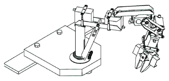
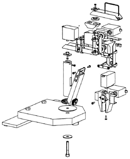
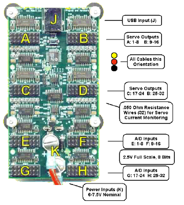
Assembled and programmed a robotic arm in a new language in under 90 minutes to perform the functional movements as seen in the our demonstration video.
I was responsible for the programming.
Lorem ipsum dolor sit amet, consectetur adipiscing elit. Ut elit tellus, luctus nec ullamcorper mattis, pulvinar dapibus leo.
Lorem ipsum dolor sit amet, consectetur adipiscing elit. Ut elit tellus, luctus nec ullamcorper mattis, pulvinar dapibus leo.
Lorem ipsum dolor sit amet, consectetur adipiscing elit. Ut elit tellus, luctus nec ullamcorper mattis, pulvinar dapibus leo.
Lorem ipsum dolor sit amet, consectetur adipiscing elit. Ut elit tellus, luctus nec ullamcorper mattis, pulvinar dapibus leo.
Academic Article on Leadership
Topic: Leadership Development in Engineering Teams: Implementing Effective Communication and Collaboration Techniques
This was an Engineering Management group task consisting of Members covering the following 5 sections: 1.Introduction, 2. Literature Review, 3. Case study Analysis, 4. Findings and Recommendations, 5. Conclusion
Below is section 3 on Case study analysis
Case Study: Ray Dalio’s Bridgewater Associates and Idea Meritocracy
By: Ipfi Munakisi // 07-07-2024
According to Samantha Rivera (2023), the eight communication techniques engineering leaders need to succeed are, engaging in Active Listening, asking questions, practicing public speaking, being clear and concise, showing empathy and lastly, receiving and applying feedback. The case study below looks at how effective communication and collaboration techniques can be implemented /used in Leadership Development as can be found in or applied to Engineering Teams.
Background
Bridgewater Associates, founded by Ray Dalio, is the most successful hedge fund in history and one of Fortune’s five most important private American companies (Sachin Waikar, 2019)
The firm is well-known for its unique approach to management and decision-making, known as “idea meritocracy.”
In a TED presentation, Ray Dalio (2017) recounts how after he had founded Bridgewater associates, he made a terrible business investment judgement/decision (wrong prediction) about how he thought the markets would react to prevailing market conditions at the time for which he was terribly wrong, and that saw him lay off all his employees and was left in debt.
(Ray Dalio TED conference, 2017),” It was one of the most painful experiences of my life, but it turned out to be one of the greatest experiences of my life because it changed my attitude about decision-making. Rather than thinking, ‘I’m right’, I started to ask myself, ‘How do I know I’m right?’ I gained a humility that I needed in order to balance my audacity. I wanted to find the smartest people who would disagree with me to try to understand their perspective or to have them stress test my perspective. I wanted to make an idea meritocracy. In other words, not an autocracy in which I would lead and others would follow and not a democracy in which everybody’s points of view were equally valued, but I wanted to have an idea meritocracy in which the best ideas would win out. And in order to do that, I realized that we would need radical truthfulness and radical transparency.”
By adhering to this mode of communication, today Bridgewater Associates is the most successful hedge fund in history.
Idea Meritocracy at Bridgewater Associates
In this case study, it is observed that Idea meritocracy is a system where the best ideas rise to the top of considerations based on their merit, regardless of the source, which encourages open dialogue, constructive disagreement, and a culture of radical transparency.
Radical Transparency
At Bridgewater, employees are encouraged to express their thoughts openly.
(Ray Dlio TED conference, 2017), “what I mean by radical truthfulness and radical transparency is people needed to say what they really believed and to see everything. And we literally tape almost all conversations and let everybody see everything, because if we didn’t do that, we couldn’t really have an idea meritocracy. In order to have an idea meritocracy, we have let people speak and say what they want.”
Even challenging the boss is fair game; the transparency ensures that all voices are heard in the organization and that decisions are made based on the best available information.
Algorithmic Decision-Making
In the same TED presentation in 2017, Ray Dalio makes admissions that he introduced algorithms (through their computer engineering and programing department) to help make decisions, and that these algorithms consider input from various team members, ensuring a more objective process. The usage of analytically driven data reduces personal favoritism and biases, resulting in a more rational and effective decision-making and outcomes.
Benefits and results of Idea Meritocracy
According to Sachin Waikar (2019) Ray Dalio is quoted saying a system of thoughtful disagreement creates competitive advantage.
The implementation of idea meritocracy at Bridgewater has led to:
- Improved Decision Quality: By considering diverse viewpoints, Bridgewater makes better decisions by having an enhanced decision-making process.
- Reduced Bias: The system minimizes personal biases and favoritism (not only idea meritocracy but the Algorithmic Decision-Making)
- Empowerment: Employees feel empowered to contribute and challenge ideas (Increased employee engagement and morale)
- Greater innovation and problem-solving capabilities
Remarks
Ray Dalio’s experience at Bridgewater taught him the value of diverse perspectives and thoughtful disagreement. This led to the firm developing a process to organize and resolve disagreements—an idea meritocracy; an approach that significantly improved the quality of decisions and cultivated a culture of continuous improvement and innovation within the organization.
This approach also encompasses eight communication techniques engineering leaders need to succeed as cited by to Samantha Rivera (2023), which include engaging in active listening, asking questions, practicing public speaking, being clear and concise, showing empathy, and receiving and applying feedback.
References
Dalio, R. 2017. TED: How to build a company where the best ideas win, 6 September 2017 [Video file]. Available https://www.youtube.com/watch?v=HXbsVbFAczg [2024, June 4th ].
Rivera, S. (2023), 8 communication techniques engineering leaders need to succeed [Online]. Available: https://online.hbs.edu/blog/post/communication-techniques [2024, May 29].
Waikar, S. 2019. Bridgewater Investments Founder Ray Dalio: Invest in Idea Meritocracy [Online]. Available: https://www.gsb.stanford.edu/insights/bridgewater-investments-founder-ray-dalio-invest-idea-meritocracy [2024, May 30].
Mock Company & Hierarchy Structure
Engineering Management

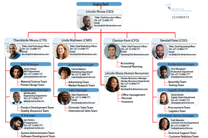
Dynamics3D is a pioneering small-scale manufacturing company headquartered in Cape Town, South Africa, with a half a decade track record in the engineering industry. The Company specializes in the design, manufacturing, and sale of medium to high-level 3D printers alongside entry-level CNC machines. Dynamics3D is revolutionizing access to additive manufacturing/3D printing technologies. This vision is carried out under the auspices of chief executive Lincoln Khoza and the stewardship of the capable management whose structure is showcased in the next page highlighting the chain of command.
Dynamics3D’s mission is twofold:
– to democratize 3D printing by offering high-quality yet affordable 3D printers and printer filament made from recycled materials, thereby lowering costs and environmental impact.
– the second fold is aiming to streamline the prototyping process to the public by providing an online platform where individuals and companies can upload their 3D designs, receive nigh-instant quotes, and have their creations printed and shipped directly to them. (with virtually no product order limit!)
This platform (accessible on our website www.dynamics3d.com) serves both domestic and some of part of international markets, making rapid prototyping a reality for innovators worldwide. Through our innovative online tool, customers can effortlessly engage with our services, enabling seamless access to advanced manufacturing capabilities.
Dynamics3D’s product range includes affordable mid-to-high caliber 3d printer (including custom made), 3d filaments and other accessories, portable entry-level CNC machines, catering to a diverse clientele seeking accessible additive manufacturing solutions.
Dynamics3D’s ethos centers on innovation, quality, and customer satisfaction. Our dedicated team constitutes skilled engineers, technicians, management staff and sales professionals committed to pushing the boundaries of additive manufacturing technology and how that can be made readily available to the public, aligning with our vision of being at the forefront of this endeavor.
By fostering a culture of continuous improvement and adaptability, Dynamics3D has garnered notable success within the engineering and additive manufacturing industry and is now focusing on more expansion and collaboration efforts.
Dynamics3D remains steadfast in its commitment to making 3D printing more accessible and empowering individuals and businesses to bring their ideas to life with ease and efficiency.
Company structure
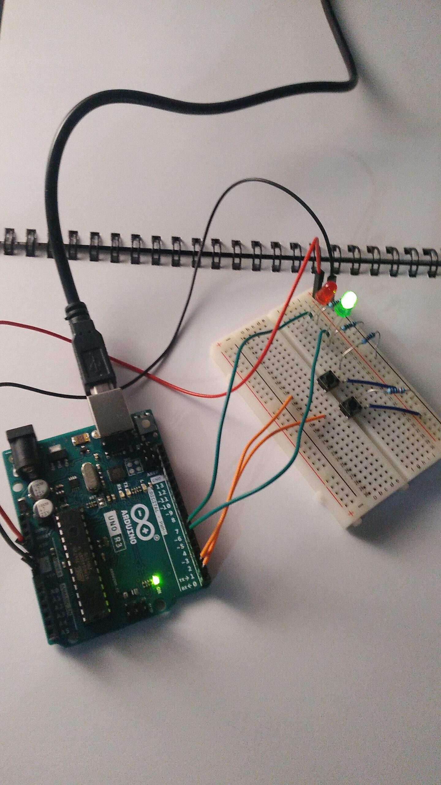
Automotive High Beam System with Dashboard LED Indicator
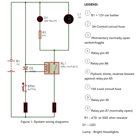
This manual provides a vehicle-agnostic design for installing a momentary switch-activated high beam system with a dashboard LED indicator, replicating OEM ‘flash-to-pass’ functionality. It is structured to guide users through theory, component selection, calculations, and installation, with a practical focus on budget-friendly sourcing (South African suppliers included) and safety-critical details like fuse selection and back-EMF suppression. Key features include datasheet-driven calculations, step-by-step wiring diagrams, and compliance notes, ensuring a reliable DIY solution for most 12V automotive systems.
Key Features
- High beams activate only while a momentary switch is pressed or toggled.
- Dashboard LED illuminates when high beams are active.
- Safe, fused, and relay-controlled design.
Tutoring Mechatronics students in Computer Engineering

Employer: Cape Peninsula University of Technology (CPUT)
Computer Engineering Mentor/Tutor in Mechatronics Department | CPUT (2022)
Worked in the mechanical and mechatronics department tutoring mechatronics students Computer Engineering focusing on the C programming language (from algorithms to flowcharts to programming), holding live and recorded online classes, and doing embedded system related administrative work including marking student papers.
First ever class on the topic “Flowcharts and algorithms”. A 5 minute introductory part
First ever class on the topic “Flowcharts and algorithms”. A 5 minute part 2
First ever class on the topic “Flowcharts and algorithms”. A 5 minute part 3